Water/wastewater
Advancing Flow Calibration for Precision Flowmeter Development
Nov 19 2025
Author:
Neil Hannay, Senior Development Engineer
on behalf of Titan Enterprises LtdFree to read
Articles are free to download. Unlock the article to be shown more content, graphs and images.
Neil Hannay reports on the investigation and resolution of calibration limitations experienced during flowmeter development for ultra-low flow applications.
Titan Enterprises supplies precision flow meters globally and operates three certified flow calibration systems to support production. These calibration rigs cover flow ranges from 2 ml/min to 200 l/min with a manufacturer’s uncertainty of ±0.05%.
The systems are based on piston provers, with linear encoder measurement of piston displacement under hydraulic or pneumatic operation. While robust and reliable for production use, these rigs are manually operated and inherently limited in versatility.
Their primary purpose being the calibration of devices through production and prior to shipment to customers.
This technical report reviews the investigation of flow rig limitations when embarking on ultra-low flow measurement and how this was overcome through the in-house development of specific calibration tools to meet R&D requirements.
Titan’s portfolio of meters currently operate accurately down to 2 ml/min, matching the traceable calibration capability of its certified rigs. Recent advances in electronics and signal-processing algorithms provide the potential to extend Titan’s ultrasonic technology to flows significantly below this limit.
To develop flowmeters in this regime, Titan needed equally advanced calibration tools.
Current Position: Calibration Capabilities and Investment in R&D
Titan’s three state-of-the-art piston prover flow calibration tools for production calibration of their meters have an overall uncertainty of ±0.25% (95% CL). The equipment installed provide accurate calibration with water from 2 millilitres per minute up to 200 litres per minute.
Annual calibration checks against certified weigh scales mean all flow meter calibrations are traceable to national standards. The production rigs are almost entirely manual in operation, being operated by our trained staff to produce 6-point flow calibration certification for each of Titan’s 10 to 15 thousand meters calibrated each year.
The calibrators use a piston within a smooth bore tube to act as a moving barrier between the pressurising control medium and the displaced test water. As the piston travels it is monitored by a linear encoder generating a continuous train of electrical pulses to indicate its position and rate.
Each pulse represents an extremely small but very precise volume of fluid, and this volumetric dispensing is then correlated to the meter under test output to calibrate its performance.
These production rigs are expensive, require continual manual operation and are being operated almost continuously during the working day.
Although the certified calibration systems are ideal for production, the limited availability due to such production demands, constrains the ability to conduct experimental work, and they also lack the flexibility required for early-stage product development.
Titan consistently invests approximately 10% of revenue in research and development, recognising that the ability to verify flowmeter performance is central to innovation. Over the years, Titan has designed a number of small developmental calibration systems.
These initially included a transfer standard system using a high-accuracy Coriolis reference meter and a small piston prover operated by a ball screw and drive motor.
These rigs enabled rapid performance assessment of prototype flowmeters and investigation of thermal effects. Absolute accuracy or stability of flow were less critical for the development of early designs of flow meter, but versatility was always a key requirement.
However, as Titan’s flowmeter technology advances, particularly in the ultrasonic range, more accurate and versatile calibration systems are essential in the assessment of new flowmeter designs.
Aim: Development Projects Driving Calibration Requirements
Two major development programmes within the scope of Titan’s ultrasonic flow measurement technology created the demand for ultra-low flow calibration:
1. Extending the Atrato® Ultrasonic Flowmeter Range – Targeting flows >10× lower than the current minimum flow rate, with measurement capability down to 0.2 ml/min or below. This would offer a competitive volumetric alternative to existing thermal low-flow devices.
2. Clamp-On Ultrasonic Flowmeter with Disposable Tubing – Designed to measure small batches of medical-grade fluids in a low-cost disposable tube. Potential applications include dialysis equipment and bolus delivery monitoring, where accuracy, sterility, and affordability
are critical.
Both projects required calibration systems capable of extremely smooth, stable, and repeatable flow delivery. Direct integration of calibrator feedback into the control system was also essential. Full automation would also allow the rigs to perform complex flow profiles and transient tests while logging detailed performance data.
Summary of Conclusion
For these development projects, the team designed hardware and software to produce smooth-flow, fully automatic calibration rigs, with a total flow range of 0.0054ml/min to 4l/min calibration capability and calculated uncertainty of 0.1%.
The software allows for multiple scenarios of operation, from long-term flow stability to short batch dispensing to be assessed with new meter designs.
With the newly designed calibration rigs we were able to take concept designs for very low flow measurement using current ultrasonic knowledge and prove the effectiveness for flows down to 0.1ml/min at accuracies of ±1% + 0.02ml/min.
In addition, the prototype designs for a clamp-on meter for use with silicone tubing on blood type liquids, were also proven to be reliable for flows of 5 to 400ml/min with linearity of ±2%.
With the versatile nature of the new calibration designs, meters were tested for linearity, repeatability, batch dispensing at multiple volumes and flow rates, as well as long-term calibration drift.
Problem: Limiting Factors
Commercial low-flow calibrators with the required accuracy and versatility were not available, and bespoke systems proved prohibitively expensive. Building on prior experience with motorised piston systems, Titan therefore committed to developing next-generation low-flow calibration rigs in-house.
Based on previous work with ball screw driven piston systems, one of the main issues encountered was the method to ensure accurate measurement of the piston movement, coupled with smooth, reliable delivery.
The commercial piston provers used controlled pneumatic or hydraulic feed and relied on linear encoder to measure the progress of the piston.
Complex and expensive as this method is, it inherently provided a good, measurable liquid flow. By moving to a mechanical threaded driver, reliance on the thread rotation and piston connection to be accurate and consistent, becomes crucial; as does fine accurate control and measurement of the motor rotation.
Investigative Journey to Expanding Calibration Capability
1. Technical Considerations in Calibration Rig Design
Designing these rigs required careful attention to both hydraulic and mechanical factors. Key considerations included:
- Achieving stable and smooth linear motion at ultra-low displacement rates.
- Optimising valve synchronisation and timing to eliminate disturbances.
- Ensuring sufficient mechanical stiffness in the drive system for accuracy.
- Accurate temperature measurement throughout the process.
- Selecting suitable, rigid liquid piping to maintain repeatability.
- Implementing an automated calibration routine for prover validation.
- A reliable system bleeding mechanism.
- Integrating safety systems, including end-of-stroke detection and overpressure protection.
On the software side, control algorithms had to be developed to ensure accurate, stable flow delivery and precise monitoring from the piston driving the flow and the meter’s pulse output whilst under test.
Full automation was to be enabled to allow the rigs to run a wide variety of test protocols, from steady-state operation to complex transient flow scenarios.
Existing software for production systems was manual and designed for operation with manually operated equipment.
Previous research tools provided the beginnings of the software for both control and measurement but would require development for the final equipment design and to be expanded for all expected scenarios of testing.
2. System Set-Up & Reference Tests
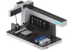
The first designs (Fig 1.) used stepper motors due to their precision of rotation and ball screw systems available off the shelf. They were found to be reliable, but the coarseness of the single ball screw meant that flow rates cycled ±1% over a few seconds.
Volume delivery calibrations were accurate enough for assessing new flowmeter designs, but the variation of flow meant it was very difficult to accurately measure scatter with a flow meter in stable operation.
Altering the drive rod to fine precision threaded lead screws gave significantly increased levels of granularity of dispensing rate and also provided a very steady and smooth flow pattern along the entire length of the piston operation.
The final designs (Fig 2.) incorporated two drive rods to give greater force. This also allowed the stepper control to be staggered between the two drives, doubling the effective granulation of control at low Hz of operation.
Fig 1. Original single ball screw driven piston prover
Fig 2. Improved precision dual screw driven piston prover
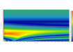
The graph below (Fig 3.) shows the improvement of smooth delivery for the original ball screw versus the precision machined dual screw operation.
The stepper motor can be controlled to deliver fine rotation at constant rate, but for the initial design the actual liquid delivery cycled with the variation on the large uneven thread on the ball screw driving the piston.
Moving to a fine precision threaded rod meant the motor operating rate was directly related to the liquid being dispensed, giving accurate and very smooth delivery.
The effective drive frequency outputs for 25Hz to 25kHz were effectively controlled to 0.04% of the set point over the entire 1000:1 range of operation.
This ensured accurate flow and volume control as illustrated in the example mass calibration of one of the 45ml/min calibrator (shown in Fig 4.) giving an effective calibration variation of only -0.01%.
Fig 3. Chart showing Flow Cycling of original design versus new design as measured by Atrato® flowmeter
Calibration Report: 45mlpm flow rate calibrator: Flow Range 0.02525 to 48.4ml/min (1.515-2,904ml/h)
Fig 4. Example Mass Calibration report on the new Piston Prover Calibrators
Moving on to develop a calibrator rated for flows well below 2ml/min, the design was miniaturised and the piston operated in reverse to further reduce the volume delivered per mm of piston movement (Fig 5. and Fig 6.).
The resultant calibration unit operated to the same uncertainty but had a range of 0.0054 to 10 ml/min. Of course, accurately calibrating this unit at the lowest flows offers its own challenges, as the lowest flow rate would mean that to deliver the full 7.5ml of piston volume would take over 23 hours.
When looking at small dispense volumes using mass reference calibration, fine accurate scales must be used and careful control of measurement must be considered, as even evaporation could give significant errors.
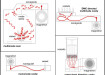
Fig 5. Low flow calibration rig design with liquid on piston side of cylinder to improve the resolution at very low flows: 0.0054 to 10 ml/min (0.324-600ml/h)
Fig 6. Main calculations for 0.0054 to 10.00ml/min low flow calibration rig
3. Challenges
Once the principle of design for the calibration equipment was decided upon, the practicalities of implementation presented several challenges. Off-the-shelf equipment is not designed for this type of application, so a significant amount of work had to be done to compensate for the differences.
For example, the decision to use stepper motors gave the advantage of precise operation, but the drivers and associated software are designed for positioning rather than velocity management.
The single steps of the motors would also offer pulsation into the system, potentially causing aliasing of measurement; so microstepping drivers implemented in both software and hardware terms with the dual drive rods effectively smoothed the delivery
Once the main operational software and hardware had been developed and tested to deliver the level of accuracy required, the process of ensuring safe, reliable operation came into play. This included piston positioning and safety cutoffs in case of over pressure, misalignment or other failure modes.
All this then linked to an easy-to-use operating software interface which offers standard traceable calibrations and adaptable, multiple flow scenario testing with the ability to expand such testing with ease. All components are designed to operate automatically, often for extended periods and sometimes for many hours at a time.
The final design addition was to implement a constant back pressure system, which could be maintained at constant value at both maximum and minimum flow rates.
This is especially important for ultrasonic flow system design, as without adequate back pressure, microbubble formation attenuate the signal, preventing reliable flow measurement.
The production calibration systems rely on a pressurised airline and sealed buffer vessel system to do this, but this option was not readily accessible for ultra-low flow designs. Instead, a hydraulic lock system was developed and implemented to give a minimum required back pressure.
Results: Ultra-Low Flow Development Using the New Calibration Rigs
The two types of meter Titan are developing have differing operational requirements.
The ultra-low flow device needs to have good linearity over the whole flow range with excellent repeatability, without compromising too much on the response time and ultimately packaged in a reasonable dimensioned housing for both end user and OEM installation.
The clamp-on device is primarily for medical applications and therefore must have good stability over a few hours or days (the typical maximum period for medical tubing systems).
It must be highly reactive with relatively fast response times and be able to measure bolus deliveries over a wide range of flow rates and volumes to mimic syringe sizes and dispense speeds.
Ultra-Low Flow Ultrasonic Flow Meter
The ultra-low flowmeter target was to investigate the feasibility of developing an ultrasonic device operating at lower flow rates than any other ultrasonic devices currently known to us.
The target was 0.2 to 20 ml/minute which is ten times lower than existing Titan devices. The production aim was to incorporate this range into our next generation Atrato® range.
Fig 7. Ultra Low Flow Meter Prototype with 1/16” tube connections
The design principle has a compromise of velocity in the flow measurement tube and length of the tube. Increasing both, increases the time-of-flight difference of the ultrasonic wave travelling in both directions.
Increasing velocity requires small bore for low flows which suffer from attenuation of signal and interference of background noise; whilst lengthening the tube makes the response of the meter much lower and suffer from loss of flow measurement signal strength.
Prototyping of a variety of configurations, together with additional novel design aspects, becomes a crucial part of development in these advanced technical breakthroughs.
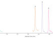
Fig 8. Example calibration 0.05 to 20ml/min flow range
The graph in Fig 8. above displays the results obtained from the fifth evolution of the ultra-low flowmeter. The 0.2ml/min target was easily achieved, and flow readings were possible down to 50 microlitres per minute under laboratory conditions.
The result provided confidence to meet the 200 microlitres per minute target for the final device when set for production.
Development work continues to optimise the flowmeter design based on the best accuracy available at reasonable response times. Novel engineering of the flow sensor element has enabled subsequent designs to improve the flow response time by a factor of 50, whilst maintaining accurate readings.
The chart in Fig 9. illustrates the results of two measurement tube flow range designs, meeting ±1.0% + 0.04ml/min accuracy with raw measurement. Calibration linear correction is expected to improve on these results for later designs.
Fig 9. Two prototypes of ultra-low flow ultrasonic meters. Accuracy of ±1% + 0.04ml/min without linear correction implemented. Measuring reliably down to 0.15ml/min. Clamp-on Ultrasonic Flow Meter
Fig 10. 3D printed clamp-on prototype with clamp sensor over silicone tube and separate display
Fig 11. Initial calibration silicone tube 5-400ml/min @ ±2% linearity
In response to a customer’s requirement for flow measurement in a disposable medical tube - specifically involving smallbore silicone tubing for plasma-type fluids delivered by peristaltic pumps - Titan developed prototypes to meet their specifications.
Initial designs based on Titan’s Metraflow® flowmeter were created using their proprietary knowledge and 3D printing capability to offer practical prototypes for the customer to test in-situ.
The prototypes were also fitted with the customer’s tubing to test the feasibility of a clamped unit. Utilising the new ultra-low flow calibration rigs enabled quick assessments to be performed on water in Titan’s in-house facilities.
The basic linearity of initial designs proved to be quite acceptable with a typical linearity of ±2% over the flow range of 5 to 400ml/min (see Fig 11.).
For such a system to operate practically in the field, it must be reliable and repeatable even when tubing is continuously removed and refitted into the housing.
Initial testing gave a variation between multiple tubes of about ±2% and only became more variable at the very low flow end as the noise level increased in the ultrasonic flow signal (Fig 12.).
Overall, the performance was better than expected and is very promising for the development of a commercial product to augment the current Atrato® flowmeter range.
Fig 12. Multiple tube replacement variation in calibration at the ultra-low flow region
Fig 13. Batch dispensing variation at different dispense volumes and flow rates
Apart from flow monitoring, volume dosing is the other key technical challenge for this type of system. Accurate and reliable dispensing measurement is a key area in the medical flow industry and again, initial trials of multiple dose scenarios enabled by the new calibration rig design, could be tested.
The graph above (Fig 13.) shows some of the results of dispensing multiple times at different flow rates and total volume dispensed.
Even at very low dosing of less than 1ml volume, the repeatability is within 5% at all flow rates - again a very encouraging result.
Working with OEM partners, Titan is developing this meter design for multiple tube sizes and materials with a focus on the medical and biopharmaceutical markets, where dosing or flow monitoring is required
Conclusions
This complex project demonstrates Titan’s in-house expertise in exploring practical resolutions to overcome limitations in R&D and expand our breakthrough technology.
By developing in-house capability for accurate and versatile meter calibration and testing, Titan can quickly advance the process from prototype to verified product. In-house proprietary software allows for rapid testing of multiple scenarios encountered by our customers, helping ensure processes are optimised.
The calibration rig design principles will enable Titan to develop and build advanced tools tailored to customer-specific needs.
Future developments include novel fluid test units and fully temperature-controlled systems, supporting the creation of cutting-edge products for both universal applications and OEM-specific solutions in the global market.
Free to read
Articles are free to download. Please login to read this article or create an account.
Digital Edition
Lab Asia Dec 2025
December 2025
Chromatography Articles- Cutting-edge sample preparation tools help laboratories to stay ahead of the curveMass Spectrometry & Spectroscopy Articles- Unlocking the complexity of metabolomics: Pushi...
View all digital editions


Events
Jan 21 2026 Tokyo, Japan
Jan 28 2026 Tokyo, Japan
Jan 29 2026 New Delhi, India
Feb 07 2026 Boston, MA, USA
Asia Pharma Expo/Asia Lab Expo
Feb 12 2026 Dhaka, Bangladesh