

Abstract
Lithium ion battery (LIB) technology is the state-of-the-art rechargeable energy storage technology for electric vehicles, stationary energy storage and personal electronics. However, a wide variety of degradation effects still contribute to performance limitations. The metallic copper and aluminium current collectors in an LIB can be subject to dissolution or other reactions with the electrolytes. Corrosion of these metal foils is significantly detrimental to the overall performance of an LIB, however the mechanisms of this degradation are poorly understood. This review summarises the key effects contributing to metal current collector degradation in LIBs as well as introduces relevant corrosion and LIB principles. By developing the understanding of these complex chemistries, LIB degradation can be mitigated, enabling safer operation and longer lifetimes.
Export citation and abstract BibTeX RIS

Original content from this work may be used under the terms of the Creative Commons Attribution 4.0 license. Any further distribution of this work must maintain attribution to the author(s) and the title of the work, journal citation and DOI.
1. Introduction
Increasing concerns related to the climate crisis and environmental pollution due to the excessive release of carbon dioxide have driven research efforts into green transportation [1 – 7]. Electric vehicles (EVs), powered by lithium ion batteries (LIBs) are of particular interest. It is expected that 64% of the UK vehicle fleet will be electric by 2030 and that this will contribute to reducing air pollution and our dependency on dirty fossil fuels [8]. In order to support this increased uptake in EVs, current LIB technology needs to be improved in multiple key areas: performance, lifetime and safety. To achieve such improvements, a comprehensive understanding of the degradation mechanisms of all components encountered during LIB operation needs to be developed in order to mitigate the processes—enabling safer operation and longer lifetimes.
A lithium ion battery is a rechargeable, secondary battery. Its operation is based on the reversible intercalation of lithium ions into a crystal structure to store and release charge [9]. An LIB cell is made up of a cathode and an anode, separated by a porous membrane, all wetted by the electrolyte as shown schematically in figure 1. The anode is usually a graphite-based slurry coated onto a copper foil that is operating as a current collector. The cathode is generally a lithium metal oxide or phosphate (e.g. LiCoO2, LiMn2O4 or LiFePO4) slurry, coated onto an aluminium foil current collector [9]. Upon charge, an electrochemical potential difference is created between the electrodes and lithium ions deintercalate from the cathode host structure. The ions are shuttled from the cathode to a higher energy state at the anode [10]. Electrons are released into an external circuit to compensate for the charge. The electrolyte, typically a lithium salt dissolved in an organic solvent, is ionically conducting but electronically insulating, forcing the electrons to the external circuit, where they can carry out work. This electricity is passed to the circuit via the metallic current collectors. The separator is electronically insulating and acts to prevent short circuit between the electrodes. However as it is wetted by the electrolyte, it allows for movement of lithium ions ensuring cell conductivity.

Figure 1. A schematic of a lithium ion battery and its components. Lithium ions are shuttled from the cathode to the anode upon charging. The ions pass through an ionically conductive but electronically resistive electrolyte towards the anode. Electrons move between current collectors through an external circuit to counter-balance the change in charge. The separator prevents short circuit.
Download figure:
Standard image High-resolution imageAs mentioned above, the current collectors serve to deliver the electronic component of the charge to the external circuit. The current collectors do not participate in the Li+ ion intercalation reactions so thin and light metal foils are preferred to increase the cell's gravimetric and volumetric energy density. The materials should be ionically insulating and electronically conductive and maintain good chemical and electrochemical stability in the electrolyte during battery operation [5, 11 – 14]. Other requirements include providing a mechanically robust framework for the cell construction—they should have good mechanical properties and should adhere well to the electrode slurries [15 – 17].
LIB research has been mostly focused on the optimisation of the electrodes and electrolyte, however little attention has been paid to the current collectors. Although the conventional wisdom is that the current collectors are stable during LIB operating conditions, numerous authors have observed their dissolution after electrochemical cycling [18 – 27]. Corrosion of these metal foils may result in loss of adhesion of the active material to the current collector, limiting the battery power and resulting in 'dead-weight' as the active component of the electrode is no longer electrochemically contacted. Corrosion products may also form and subsequently interfere with normal operation of the battery, reducing lithium ion mobility and decreasing electronic conductivity, resulting in a loss of cell capacity [18, 19, 22, 28 – 30]. An increase in electrical contact resistance at the electrode–current collector interface due to corrosion and corrosion product formation can result in an energy loss of up to 20% of the total energy flow in and out of a battery under normal operating conditions [31]. In addition, current collector dissolution can potentially lead to cell short circuits impacting the safety of batteries [32 – 35]. Such a short circuit can result in a sudden increase in current, leading to rapid increase in cell temperature and possible catastrophic failure. Although it is clear that current collector degradation can be detrimental to overall LIB performance, the mechanisms of their degradation are poorly understood. Further, due to the complex and interlinking nature of LIB degradation, the contribution of current collector degradation to long term cycling performance has not been thoroughly investigated. This review summarises the key effects contributing to metal current collector reactions/dissolution in LIBs, as well as highlighting areas where this understanding can be further understood. In particular, we find that correlating current collector degradation to overall cell performance has been mostly overlooked. This paper also provides a brief introduction to some basic corrosion principles and LIB operation principles, with the aim of providing a solid foundation of knowledge to researchers from multiple fields, enabling the comprehension of degradation phenomena from a variety of new perspectives.
2. LIBs
2.1. LIB: operating principles
The release of electrons into an external circuit results from the pair of chemical 'half-reactions' that occur at the electrodes. These reactions are in principle reversible, giving the cell its rechargeable nature. The difference in voltage between the couples of both electrodes (for example Fe2+/Fe3+ paired with Li/Li+ in an LiFePO4/Li cell) determines the overall cell voltage. The energy density of the cell can be calculated according to equations (1) and (2) for the gravimetric and volumetric energy densities respectively, where  represents the average voltage and Q represents charge [9]:


Most commercial cells are composed of an LiCoO2 cathode and graphite anode [36]. State-of-the-art EVs employ LiNiMnCoO2 or LiNiCoAlO2 cathodes and a lot of research is focused on improving the performance of these materials [37]. The electrode active materials are mixed with a high surface area carbon black (to improve conductivity) and a polymeric binder, generally polyvinylidene fluoride at the cathode (to maintain contact between all components) and coated onto the current collector. The cell is assembled in a discharged state, with all Li+ ions in the host oxide at the cathode. Upon application of a potential difference, the Li+ ions deintercalate from the transition metal oxide and are inserted into the graphite at the anode. Upon discharge, Li+ ions are removed from the graphite and intercalate back into the metal oxide host framework. These intercalation reactions result in the production and consumption of electrons which move through an external circuit to balance the charge. The anodic, cathodic and overall cell reactions are as follows [9]:


Intercalation type cathodes have dominated the commercial LIB market since their first commercial implementation by Sony [38]. Such cathodes have a host structure that enables the reversible hopping of Li+ ions for example 1D tunnels in the case of LiFePO4 or 2D layers in the case of LiCoO2 [9]. Such materials are of interest as they are able to maintain their structure upon removal and insertion of lithium, allowing for good capacity retention as a function of cycling.
Lithium metal could be used as the anode in an ideal case as it provides a high specific capacity of 3680 mAh g−1 [39]. Unfortunately, lithium metal does not plate and strip uniformly as a function of cycling and it forms dendrites at the electrode surface—as these grow, they may pierce the separator, coming into contact with the cathode and causing a potentially dangerous short circuit [39]. Graphite is therefore mostly employed at the anode as it avoids this safety concern, although it also provides a lower energy density. It should be noted however, that lithium dendrite growth has still been observed on graphite [40].
LIB electrolytes consist of a lithium salt (generally LiPF6) in a mixture of organic carbonate solvents. These solvents are usually some combination of ethylene carbonate (EC), ethyl methyl carbonate (EMC), diethyl carbonate (DEC) or dimethyl carbonate (DMC). These carbonates have low viscosity, poor electronic conductivity, good ionic conductivity and have relatively good chemical stability [39]. LIB cells are assembled in a dry environment (e.g. a glovebox or dry room) to avoid LiPF6 salt hydrolysis, which forms hydrofluoric acid (HF). Cells can be assembled in a variety of configurations, with the most common experimental configurations being pouch cells and coin cells. Coin cells seal the cell components in a stainless-steel casing and pouch cells are polymer pouches that contain the components and have conductive foil tabs welded to the electrodes.
The rate at which a battery is charged/discharged is given in terms of the C-rate. A charge or discharge current of 1 C is the current required to charge or discharge an electrode in 1 h (assuming 100% theoretical capacity). A C-rate of C/2 and 2 C will charge or discharge fully in 2 and 0.5 h respectively.
2.2. Solid–electrolyte interface (SEI)
An LIB cell's open circuit voltage (VOC) is dependent on the electrode potentials of the anode and cathode, μA and μC respectively according to equation (7) [9]. Stable operation of the battery requires that this voltage lies within the stability window for the electrolyte, Eg, defined by its highest energy occupied molecular orbital (HOMO) and lowest energy unoccupied molecular orbital (LUMO) as described in equation (8) and seen in figure 2:


Figure 2. Open circuit molecular orbital diagrams of a lithium ion battery where the anode and cathode electrochemical potentials lie (a) within the electrolyte stability window and (b) outside the electrolyte stability window, resulting in SEI formation. Adapted with permission from [9]. Copyright (2013) American Chemical Society.
Download figure:
Standard image High-resolution imageIf the LUMO of the electrolyte is lower than μA (the anode potential), it will be electrochemically reduced. Similarly, if the electrolyte HOMO is greater than μC (the cathode potential), it will be oxidised. In an aqueous electrolyte, the above reactions are hydrogen and oxygen evolution respectively, limiting the maximum voltage of an aqueous cell to less than 2 V [36]. Commercial batteries therefore employ non-aqueous electrolytes which have a wider Eg in order to maximise the cell voltage and hence energy density.
The μA of a lithium metal or graphite anode lies beneath the LUMO of most non-aqueous organic electrolytes [39]. The electrode's operation is therefore dependent on the formation of a 'passivation' layer, known as the SEI [41]. Upon initial application of a potential, the electrolyte is reduced, forming the SEI, an electronically insulating but ionically conductive layer. These properties prevent further reaction of the electrolyte with the anode, allowing the cell to operate at voltages greater than 4.0 V. Similar layers may also form on LIB current collectors, influencing their corrosion behaviour.
3. Corrosion principles
In order to understand the degradation of current collectors in LIBs, it is helpful to understand some basic corrosion principles. In particular for LIBs, active dissolution vs. passivation and localised corrosion (including pitting corrosion and crevice corrosion) are of interest.
Corrosion is a detrimental electrochemical process relating to oxidation of a metal M to form a (dissolved) metal ion Mn + plus n electrons (see equation (9)). These electrons are consumed in corresponding, separate, reduction reactions—the oxidation is typically coupled to an electrolyte reduction reaction. The corrosion rate of a metal is determined by the net rate of these oxidation-reduction couples which is dependent on the electrochemical potential established across the metal/electrolyte interface. In organic battery electrolytes, the electrons are consumed via the reduction of the organic solvents (such as EC or DMC for example—see equations (10) and (11)) [42]. The tendency of a metal to form metal ions in a solution depends on its standard electrode potential for the M/Mn + reaction. This represents the thermodynamic driving force for the metal dissolution. In passive electrochemical conditions, the oxidation reaction of the metal results in the formation of a thin, passive film on the metal surface, which acts as a barrier to further oxidation (and is discussed in further detail below). The dissolution of metals is therefore also dependent on their tendency to passivate and the relative stability of the formed passive film:


3.1. Passivation
Reactive metals form a thin passive layer on their surfaces under ambient or submerged conditions—typically oxides or oxy-hydroxides. They kinetically restrict dissolution and further reaction of metals and alloys despite the strong thermodynamic driving force for oxidation. These films can vary in thickness, composition and properties, depending on the metal on which they form. Semi-conducting passive films form on Fe, Cr, Ni and Cu and will only grow up to a few nanometres in thickness. Insulating oxide films grow on so-called valve metals such as Al, Nb, Ti and Ta and these materials can be further oxidised by application of an external voltage (anodisation) to produce significantly thicker surface films. Passive films exhibit a potential drop at both the metal–film and film–electrolyte interfaces, as well as within the passive layer. The electric field strength within the passive layer is therefore extremely high and enables the migration of ions through the film at room temperature [43]. Although their properties and formation are different, it is interesting to note the similarity between the SEI on a battery electrode and a passive film on a reactive metal.
The structure and chemistry of passive films have been extensively studied and they have been shown to have complicated structures made up of nanoscale layers of oxides and hydroxides. The structures and compositions are dependent on electrode potential (and redox history), metal and electrolyte composition. The native/passive oxide on copper is usually proposed to be crystalline and a combination of copper I and II oxides. The native/passive oxide that forms on aluminium is very temperature dependent and can even be amorphous [43].
3.2. Pitting corrosion
Pitting corrosion is a type of localised corrosion that takes place at passivated metal surfaces in the presence of 'aggressive' anions, such as halides [43]. Pit formation generally happens in two phases and is depicted in figure 3: breakdown of passivity and pit initiation/pit growth—the growth being particularly stabilised by halide species. Pit growth stops upon repassivation. Pitting is generally considered to be an autocatalytic process: once a pit starts to grow, local aggressive conditions develop such that further pit growth is accelerated. The dissolution remains localised and the anodic and cathodic reactions separate spatially on the metal surface during corrosion.

Figure 3. Diagrams showing the pitting corrosion process on a passivated metal in the presence of aggressive fluorides like those found in battery electrolytes. (a) A passivated metal in an electrolyte, (b) the formation of a corrosion pit, blocking repassivation, (c) the growth of the corrosion pit.
Download figure:
Standard image High-resolution imageThere are various theories to describe the initial breakdown of passivity—the initiation phase—and these may depend on the environmental conditions of the film. For metals, the initiation mechanisms can be categorised as penetration, film breaking or adsorption. For alloys, pits usually initiate a local heterogeneities, such as inclusions, secondary phases or mechanical damage [44]. It is the least understood aspect of pitting and there is no consensus of a generalised mechanism. The critical factors affecting pitting corrosion in aqueous systems have been thoroughly reviewed by Frankel [44].
3.3. Crevice corrosion
Crevice corrosion is another form of localised corrosion that can occur in specific geometries or as 'under-deposit'. It occurs when a part of a metallic surface is in contact with a small volume of confined, stagnant liquid but most of the surface is in contact with the bulk environment [45]. Such an area is found in a 'crevice' as seen in figure 4. Zones susceptible to crevice corrosion may arise from a variety of situations. These include a limited mass transport by diffusion or convection between the inside of the crevice and the bulk environment, and significant solution resistance between the inside and outside of the crevice.

Figure 4. Diagrams of a passivated metal in an electrolyte showing (a) a crevice zone, with reduced mass transport via migration or diffusion and a solution resistance between the crevice gap and bulk solution (IR drop) and (b) breakdown of the metal passive layer and dissolution damage in the crevice. Adapted from [45] 2011, permission of the publisher (Taylor & Francis Ltd, www.tandfonline.com).
Download figure:
Standard image High-resolution imageThe change of the local environment inside a crevice zone into more aggressive conditions results in crevice corrosion. On passivated metals, these conditions must become severe enough to breakdown the passive film and begin metal dissolution. Such a local change in environment takes place in two steps.
Firstly, the crevice experiences a local accumulation of corrosion products or exhaustion of reactants due to restricted transport kinetics. A Galvanic cell is then developed between the crevice and the external surfaces. This in turn results in a difference in corrosion potential on the inside and outside of the crevice due to solution resistivity (known as IR drop, where I is current and R is resistance). The build-up of the Galvanic cell also further modifies the crevice environment due to electrolytic migration between the crevice and bulk solution. Once the local environment becomes severe enough to break passivity, dissolution damage occurs in the crevice.
The severity of the crevice corrosion is dependent on the crevice geometry, external surface composition, IR drop (which is dependent on crevice geometry and solution conductivity), electrolyte composition and temperature.
4. Copper current collector degradation
Copper was chosen as the current collector for the anode because it is generally stable in the LIB environment at anodic potentials [1]. Degradation of the copper metal has however been observed [46 – 49]. Whilst the degradation has been mostly observed (and indeed studied) under over-discharge conditions, some degradation has also been observed under normal operating conditions. The thermodynamic equilibrium potential for copper dissolution is 3.92 V vs. Li/Li+, well away from the potentials usually experienced by the anodic current collector during standard LIB operation. Copper current collector degradation is influenced by: applied potential (over-discharge), interactions with the battery electrolyte, the metal's microstructure and its graphitic coating. Details of the copper current collector passivation and degradation are discussed here in further detail. All potentials in this section are vs. Li/Li+ unless stated otherwise.
4.1. Passivation and the effect of potential
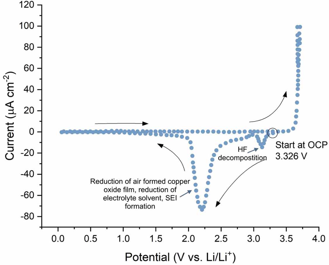
Copper foils used as current collectors have a native oxide layer, which would be formed in air. Figure 5 shows a cyclic voltammogram (CV) of a copper current collector foil undergoing an initial polarisation. The CV is measured in an LiPF6 based electrolyte, at 40 °C and in the range of 0–5 V at a scan rate of 10 mV s−1 [47]. The CV begins at open circuit potential (3.326 V) and is initially polarised in the cathodic direction. A peak is observed at ∼3.1 V which is thought to correspond to decomposition of HF impurities contained in the electrolyte [30]. Other reports indicate that HF decomposition takes place between ∼1.8 and 2.4 V via HF dissociation and subsequent hydrogen evolution and LiF deposition [50]. In this case, the peak observed at ∼3.1 V is more likely to correspond to copper reduction. A large cathodic peak is also observed in the range of 1.5–3 V. This peak is thought to be due to the reduction of the native copper oxide film to metallic copper and the reduction of the electrolyte solvent, resulting in SEI formation on the metal surface [30, 47, 51]. However, these effects have not been studied extensively and their elucidation would be valuable for understanding copper current collector degradation and its contribution to overall cell capacity fading. No anodic reactions are observed up to about 3.7 V. Further polarisation to higher potentials results in an abrupt increase in current due to copper dissolution into the electrolyte. Myung et al investigated the surface of the copper metal with time of flight secondary ion mass spectrometry (ToF-SIMS) after polarisation in an LiPF6 electrolyte and found that no significant passivation layer had formed [47]. Note that the sample was transferred through air. More recently however, Menkin et al observed an SEI layer formed on copper current collectors both after exposure to an LIB electrolyte and electrochemical cycling [52]. The implications of these findings for LIBs are discussed in more detail in this section.

Figure 5. A cyclic voltammogram of a copper current collector in a pouch cell configuration measured upon initial polarisation in the voltage range of 0–5 V vs. Li/Li+ at a scan rate of 10 mV s−1. The CV was measured at 40 °C. The counter and reference electrodes were both lithium metal and the electrolyte was 1.0 M LiPF6 in a mixture of EC and DMC. The authors assign the peak at ∼3.1 V to HF decomposition however this is more likely to correspond to copper reduction with HF decomposition taking place between ∼1.8 and 2.4 V. Adapted from [47], Copyright (2009), with permission from Elsevier.
Download figure:
Standard image High-resolution imageOver-discharge is detrimental to the copper foil current collector on the anode. Under normal operation of an LIB cell, over-discharge should not occur. However, in many LIB applications, including EVs, the cells are connected in series, forming a battery pack, in order to provide the high amounts of energy and power required. A significant difference in cell capacity can be present within such a pack, broadening the so-called capacity band and limiting the battery's capacity to that of the lowest capacity cell. This means that during battery operation, variable voltages will be experienced by the various cell's electrodes, and some will even experience over-charge and discharge. Over-charge and discharge can also occur during faulty operation of an LIB [53 – 57].
As discussed previously, a cell's potential is calculated by the difference in potential of the anode and cathode. Normal operation of an LIB is dependent on the materials used at the anode and cathode, however is generally ∼2.5–4.2 V. This means that the potential experienced by the copper anode varies between 0 and 1.5 V. At such potentials, copper should be cathodically protected (thermodynamically below its oxidation potential) and not subject to dissolution. The open circuit voltage of an LIB is generally above 3 V [26, 58]. The production of univalent copper takes place as follows in a non-aqueous environment:

Equation (12) has a thermodynamic equilibrium potential 3.566 V in aqueous electrolytes under standard conditions [18]. Under non-aqueous conditions, this thermodynamic data no longer holds [18]. The potential at which equation (12) takes place has been measured experimentally and is listed in table 1. In one case it is measured to be at around 3.92 V in an LIB electrolyte, well away from the potentials experienced by the anodic current collector during standard LIB operation [54]. Copper dissolution is therefore mostly observed in LIBs upon over-discharge, when the anode potential reaches voltages greater than ∼3.5 V [18, 47, 54, 58 – 62].
Table 1. A list of measured copper oxidation and reduction potentials in LiPF6 based electrolytes.
| Potential (vs. Li/Li+) and proposed corresponding oxidation reaction | Potential (vs. Li/Li+) and proposed corresponding reduction reaction | Electrolyte | Cell | Ref |
|---|---|---|---|---|
| 3.3 V, Cu dissolution | 1.5–3 V, reduction of the air-formed copper oxide, reduction of solvent and formation of SEI on Cu | 1 M LiPF6 in ethylene carbonate (EC)/dimethyl carbonate (DMC) (1:1) | Pouch cell, WE: Cu, CE: Li, RE: Li | Myung et al [47] |
| Above 3.5 V, oxidation of Cu | 2.95–3.8 V, reduction of Cu(II) to Cu(I) and Cu(I) to Cu | 1 M LiPF6 in propylene carbonate (PC)/EC/DMC (1:1:3) | Home made three electrode cell, WE: Cu, RE: Li, CE: Pt | Cui et al [60] |
| 3.6 V, oxidation of Cu | ∼3.4 V, reduction of Cu(I) | 1 M LiPF6 in PC/EC/DMC (1:1:3) | Home made three electrode cell, WE: Cu, RE: Li, CE: Pt | Zhao et al [58] |
| 3.6 V, oxidation of Cu | ∼3.4 V, reduction of Cu(I) | 1 M LiPF6 in EC/DMC/methyl ethyl carbonate (MEC) (1:1:1) | Home made three electrode cell, WE: Cu, RE: Li, CE: Pt | Zhao et al [58] |
| 3.65 V, oxidation of Cu (oxidation peaks are larger in consecutive CVs) | 3.0–3.6 V, reduction of copper ions | 1 M LiPF6 in EC/DMC/MEC (1:1:1) | Home made three electrode cell, WE: Cu coated with graphite and binder, RE: Li, CE: Pt | Zhao et al [63] |
| 3.70 V, oxidation of copper | N/A | 1 M LiPF6 in PC/EC/DMC (1:1:3) | Home made three electrode cell, WE: Cu coated with graphite and binder, RE: Li, CE: Pt | Zhao et al [63] |
| 3.92 V, oxidation of Cu to Cu(I), 4.17 V (oxidation of Cu(I) to Cu(II) | 3.28 V, reduction of Cu(II) to Cu(I), 3.19 V, reduction of Cu(I) to Cu | 1.2 M LiPF6 in EC/EMC (3:7) | WE: Cu, RE: Li, CE: Pt | He et al [54] |
Figure 6 shows the potential of the anode, cathode and cell during (a) normal operation and (b) upon 20% over discharge (120% depth of discharge) of an LiFePO4 vs. graphite cell, with a lithium strip reference electrode. During normal operation, the anode reaches potentials between 0.2 and 0.9 V. Upon over-discharge, the anode potential increases sharply to more than 4 V. At these potentials, copper oxidation/dissolution is very likely to take place.

Figure 6. The potential variation at room temperature of a full cell and its anode and cathode versus time during (a) a normal charge/discharge cycle (1 C) and (b) a charge/ over-discharge cycle (1 C) of a three electrode cell (cathode: LiFePO4, anode: graphite, reference: lithium, electrolyte: 1.20 M LiPF6 in EC/EMC (3:7)). It can be seen that the anode potential increases drastically upon over-discharge. Apdated from [54]. © IOP Publishing Ltd. All rights reserved.
Download figure:
Standard image High-resolution imageFigure 7 shows a CV of copper in an LiPF6 based electrolyte, with a platinum counter electrode and lithium reference electrode, measured over the potential range 2.50 V to 4.50 V. The oxidation peaks for Cu to Cu(I) and Cu(II) are observed at 3.92 V and 4.17 V respectively. The reverse reduction reactions can also be observed at 3.28 V and 3.19 V.

Figure 7. Cyclic voltammetry of copper in 1.20 M LiPF6 in EC/EMC (3:7) electrolyte (CE: Pt, RE: Li) over a potential range of 2.50 V to 4.50 V. The CV shows oxidation peaks of Cu to Cu(I) and Cu(II) at 3.92 V and 4.17 V respectively, and the reverse reduction reactions at 3.28 V and 3.18 V. CV was measured with a scan rate of 2.0 mV s−1. Adapted from [54]. © IOP Publishing Ltd. All rights reserved.
Download figure:
Standard image High-resolution imageThis is just one example of copper oxidation and reduction in LIB electrolytes. Table 1 shows a list of copper oxidation and reduction potentials that have been measured for a variety of LiPF6 based electrolyte systems.
Thermodynamically, copper dissolution is only expected at potentials greater than 3.5 V. In practice, the presence of water contamination can shift the threshold for copper oxidation to more negative potentials. The presence of impurities can lead to significant copper corrosion at OCP (discussed in further detail in section 5.2). Therefore, in an industrial setting, lithium ion cells' formation protocols include what is known as a tap charge. During a tap charge, cells are charged up to and held at a cell potential of 1.5 V in order to insert a small amount of lithium ions into the graphite on the anode, driving the anodic potential negative of the copper corrosion threshold [64]. This should be done as soon after electrolyte filling as is practical and before the cells are rested for electrolyte wetting. This tap charge step can be overlooked by academic battery researchers, however, it is an important step for minimising copper dissolution and further cell degradation.
Once Cu has dissolved, it will cause a cascade of chemical, electrochemical and electrical phenomena elsewhere in the cell. Cu+ ions can be redeposited on the anode as Cu metal, potentially forming dendrites that can grow and eventually penetrate through the separator, resulting in short circuit and cell failure [18]. Copper has correspondingly been detected throughout over-discharged LIB cells by various techniques. Zhang et al detected copper on the anode with energy dispersive x-ray spectroscopy (EDS) (as seen in figure 8) and x-ray powder diffraction (XRD) [65]. Li et al observed copper on both the anode and cathode with inductively coupled plasma—optimal emission spectrometry [28]. Maleki et al, using EDS, observed copper on both sides of the separator with EDS, confirming the proposal that copper is able to crossover through the separator [34]. Further similar observations have since been made of copper on both sides of the separator following over-charge, again however, the implications on long term cycling are not well understood [53, 54, 66].

Figure 8. EDS mapping of a carbon-based anode from a dismantled over-discharged (115% depth of discharge) commercial cell. The cathode was LiCoO2 and the electrolyte was LiPF6 based. It can be seen that copper has dissolved and redeposited on the anode. Reprinted from [65], Copyright (2015), with permission from Elsevier.
Download figure:
Standard image High-resolution imageSuch copper dissolution and redeposition can have significant consequences on the operation of the LIB. As mentioned already, the redeposition of metallic copper is thought to result in dendrite growth. He et al observed a sharp temperature increase to 120 °C after over-discharging to 120% depth of discharge (DoD) of an LiFePO4 cell, indicating short circuit [54]. They proposed that during over-discharge, Cu+ cations are formed and diffuse through the separator to the cathode, where they are reduced back to metallic Cu and form dendrites, eventually leading to short circuit. This shorting behaviour can lead to unpredictable cell cycling and possibly catastrophic failure [32 – 35].
The copper may also redeposit on the anodic SEI, modifying its 'passivating' properties and impeding lithium mobility. Maleki reported an impedance increase of 250% after over discharging to 0 V, accompanied by a capacity loss of almost 65% [34]. The presence of copper throughout the cell may have many consequences including modifying the gas evolution and consumption (and hence swelling) behaviour in the cell [28, 34, 66, 67].
The extent of degradation of cell performance has been reported to be dependent on extent of over-discharge and C-rate [53, 54]. An LiFePO4 vs. graphite cell functioned for 110 cycles at 1 C when over-discharged by 5%. When the same cell chemistry was over-discharged by 20%, it only survived two cycles [53]. Interestingly, over-discharged LiFePO4 vs. graphite cells cycled at 0.1 C formed significant copper deposits on the cathode surface whereas cells cycled at 1 C only formed minor deposits that were more uniformly distributed. This effect occurs because the copper will experience the potential resulting in corrosion for significantly longer when cycled more slowly.
It is also interesting to note that researchers have observed copper current collector foil degradation, even under standard cell operating conditions. Dai et al studied LiCoO2 vs. graphite cells and observed a degradation of the foil's mechanical properties upon standard cycling at 0.5 C, 0.8 C and 1 C for 200 cycles that became more severe with increasing C-rate (as can be seen in figure 9) [46]. The mechanical properties affected include elastic modulus, fracture strength, elongation and adhesion strength between the copper and the graphite coating. This study also observed the formation of pits on the Cu surface upon standard cycling, indicating localised rapid dissolution. The number and size of pits also increased with increasing C-rate. Although the effect of these pits on electrochemical performance is not explicitly discussed here, such pits can have significant implications on the electrode coating adhesion and therefore electrical contact. This loss of contact would result in decreased cell capacity and inhomogeneous current distribution that could lead to dendrite growth. Further studies that correlate the extent of pitting in copper current collectors to the extent of degradation in cell performance would be valuable.

Figure 9. SEM images showing the surface morphology of copper foils (a) as received, (b) after 200 cycles at 0.5 C, (c) after 200 cycles at 0.8 C, (d) after 200 cycles at 1.0 C. The cells were commercial graphite vs. LiCoO2 pouch cells, cycled from 3.0 V to 4.2 V vs. Li/Li+ in an LiPF6 based electrolyte (concentration and solvent mixture unknown). Pinholes formed on the copper current collector surface as a function of cycling, and become more apparent after cycling at faster C-rates. Reprinted from [46], Copyright (2019), with permission from Elsevier.
Download figure:
Standard image High-resolution imageThe mechanisms of how this copper dissolution takes place and influences the capacity fading, gas evolution, general stability and long term performance of LIBs is not fully understood, however it is clear that understanding these effects would be beneficial for the improvement of LIBs.
4.2. Effect of electrolyte
Copper dissolution has been observed directly upon exposure to the LiPF6 based LIB electrolyte. The condition and composition of the electrolyte were found to influence the extent of this dissolution. Zhao et al used atomic absorption spectroscopy to observe that copper dissolution increased by up to several hundred ppm when a copper foil was exposed to an electrolyte that had been aged for six months versus a fresh electrolyte [48]. This is believed to be due to the higher levels of HF present in the aged electrolyte (from LiPF6 salt decomposition). Copper dissolution was also observed upon cyclic voltammetry in the potential range 0–3.0 V by bulk electrolysis measurements. It was found that copper dissolution increased considerably in electrolytes doped with 500 ppm H2O and 1000 ppm HF in both graphite coated and non-coated copper current collectors [58, 63].
The presence of HF in the electrolyte can contribute to copper corrosion. Dai et al reported significant pitting and even micro-cracks in copper current collectors after 720 h of immersion in an LiPF6 based electrolyte (as seen in figure 10) [49]. This pitting was attributed to water impurities: related to the fact that in the presence of trace amounts of water, copper oxide is formed (equation (13)). Additionally, the LiPF6 salt decomposes in the presence of water to form HF (equation (14)). Dissociation of this HF leads to a significant drop in pH and significant dissolution of copper oxide (equation (15)). The EDS spectrum in figure 10 shows that Cu, F, O and P elements are detected at the pitting sites. This suggests that corrosion products of copper fluorides and copper oxides are formed and the LiPF6 salt decomposes. The authors do not investigate the effect of HF on metallic copper:


Figure 10. The corroded surface of copper foil after immersion in an LIB electrolyte, 1.0 M LiPF6 in a mixture of EC, EMC and DMC (1:1:1) for 720 h. (a) EDS spectrum of the corrosion products found inside the highlighted pit in (b), (b) shows the SEM image of the metal surface, pitting corrosion and cracks are visible. Adapted from [49]. CC BY 4.0.
Download figure:
Standard image High-resolution imageShu et al stored copper foils in an LiPF6 based battery electrolyte at room temperature for one month [21]. Upon removal, EDS and x-ray photoelectron spectroscopy (XPS) detected a surface film on the foil, composed of copper compounds, carbonate groups, alkyl groups, fluorides and phosphates. This film is likely to have formed from spontaneous decomposition of the electrolyte salt and solvents and trace impurities in the electrolyte.
Recently, Menkin et al investigated surface films formed on copper current collectors in the context of 'anode-free' LIBs, which are cells that employ a thin layer of lithium metal electroplated on copper as an anode [52]. The study found via XPS, nuclear magnetic resonance (NMR) and ToF-SIMS that a native interphase layer (native-SEI) is formed instantly upon copper immersion in an LiPF6 based electrolyte. This layer was found to mostly be made of LiF however its nature was found to be very dependent on the copper interface composition and homogeneity. Upon electrochemical cycling, the surface film at the copper interface was observed to grow (electrochemical-SEI) and parasitic lithium plating was observed with in situ NMR. The morphology of the plated lithium was dependent on the homogeneity of the native-SEI. Interestingly, preferential plating was found, with XPS and ToF-SIMS, to be dependent on the distribution of the ionic conductivity of the SEI compounds rather than the electronic conductivity. This uneven plating and stripping can lead to dangerous dendritic short circuits and so this study highlights the important implications of understanding the formation and nature of the SEI on copper current collectors [68]. ToF-SIMS also detected copper oxides in the electrochemical SEI however this did not seem to result in preferential plating. The role and nature of dissolved copper deposited in the SEI is not well understood, however would be of significant interest for further study.
Although the interactions of the electrolyte with the copper current collector are now being investigated, further study into this chemistry would be valuable. In particular, understanding what implications the copper SEI has on LIB electrochemical performance and how/whether it plays a role in protecting against dissolution would be of interest.
4.3. Effect of copper microstructure
The microstructure of the copper foils has also been shown to influence the corrosion behaviour of current collectors in LIBs. Kim et al heated copper current collector foils (in air) to temperatures ranging from 100 °C to 500 °C [69]. Upon heating above 200 °C, amounts of Cu3O4 and CuO measured by XRD increased considerably, with a concurrent increased surface roughness. These copper oxides formed nanoscale needle-like features on the surface as seen in figure 11. Upon cycling these bare, heat-treated Cu films against lithium (at a constant current of 0.05 mA for 100 cycles), non-negligible capacities were observed for the foils heated above 200 °C. This extra capacity is attributed to the electrochemical reactions of the copper oxides formed upon heat treatment, with lithium ions via conversion reactions [69].

Figure 11. SEM images showing the microstructure of thermally treated copper foils at (a) 100 °C, (b) 200 °C, (c) 300 °C and (d) 400 °C. Reprinted from [69], Copyright (2013), with permission from Elsevier.
Download figure:
Standard image High-resolution imagePitting has been observed on copper current collectors (see figure 12) [25]. Copper foils were polarised in LiClO4 based electrolytes (1 mA cm−2 for 300 s) and examined with scanning electron microscopy (SEM). The pitting direction was further examined with cross-sectional SEM. It was found that the corrosion direction is dependent on the crystallographic orientation of the copper grain—so called 'etch pitting'. Further, solid corrosion products were not observed in the etch pits or on surface defects, indicating that this anodic polarisation of copper causes a typical activated dissolution reaction. The implications of this copper dissolution are poorly understood but could have significant effects, on the properties and growth of the anodic SEI for example. It is therefore of interest to further explore the effects of microstructure on copper dissolution behaviour.

Figure 12. SEM images of the corroded surface of copper after polarisation in 1 M LiClO4 in PC, at 1 mA cm−2 for 300 s at a magnification of (a) 1000× and (b) 10 000×. Reprinted from [25], Copyright (2001), with permission from Elsevier.
Download figure:
Standard image High-resolution image4.4. Effect of graphite coating
The effect of the graphite coating on the electrochemical stability of copper current collectors has been investigated [58, 63, 70 – 72]. Most reports suggest that the graphite coating provides protection against copper dissolution. This could be due to different dissolution kinetics as the graphite coating may act as a diffusion barrier, protecting the copper surface. Zhao et al observed this protective effect against copper oxidation in potentiostatic polarisation experiments [63]. Additionally, CV experiments showed that the graphite coating shifted the copper oxidation by 50 mV positive of the uncoated copper (figure 13) [63]. The positive shift decreases with increasing scan number. The CV for the coated copper also shows an increase in current with increasing scan number, whereas the uncoated copper shows reproducible behaviour with cycles. The authors concluded that this is due to the initially oxidised ions being redeposited back on top of the graphite, meaning that uncoated copper is present in subsequent cycles and the geometric surface area of copper in contact with the electrolyte varies. The implications on the electrochemical performance of the anode after this redeposition of copper are poorly understood, nonetheless, it is clear that there is a significant effect.

Figure 13. CVs of (a) a graphite coated copper current collector (forward potential limit of 3.7 V) and (b) a non-coated current collector (forward potential limit 3.6 V) in 1 M LiPF6 in a mixture of EC, DMC, MEC (1:1:1) electrolyte. The uncoated current collector shows much more reproducible current responses than the coated copper. Adapted from [63]. © IOP Publishing Ltd. All rights reserved.
Download figure:
Standard image High-resolution image5. Aluminium current collector degradation
Aluminium is the current collector used at the cathode in an LIB. Aluminium is used because of its low price and good electric conductivity [73]. Aluminium also shows pronounced corrosion resistance at cathodic conditions due to the formation of passive layers in the LIB electrolyte environment. Although, aluminium shows good behaviour in LIBs, it is not corrosion free [22, 39]. Figure 14 shows a change in the thickness of the aluminium current collector of an LiNiMnCoO2 vs. graphite pouch cell that have been cycled until reaching 80% state of health. Rahe et al suggested that this thickness change is due to corrosion of the metal upon cycling [22]. Aluminium corrosion can result in significant cell degradation and performance loss as well as complicate cell recycling and use in second life applications [74]. For example, dissolved aluminium can redeposit on the active cathode material, inhibiting lithium intercalation and increasing electrical resistance. Further, Al3+ ions can also migrate to and deposit on the anode, influencing the performance of the anodic SEI. As with the copper current collector, aluminium current corrosion can also be problematic by causing parts of the electrode to lose contact with the active cathode material. It should also be noted that LIB cathodes sometimes employ aluminium coatings to mitigate cell degradation. Fully understanding aluminium's dissolution behaviour and reactivity, and any ensuing effect on LIB chemistry will be valuable for these applications too. The corrosion behaviour of aluminium current collectors is influenced by the application of a potential, the electrolyte composition, the foil's coating and its microstructure. These influences will be discussed in further detail here. All potentials in this section are vs. Li/Li+ unless stated otherwise.

Figure 14. X-ray CT image of a pristine and aged (80% state of health) commercial NMC111 cathode. The anode used for cycling was graphite and the electrolyte was LiPF6 in a mixture of EC, EMC and DEC. The exact electrolyte composition is unknown. The aluminium current collector has undergone obvious degradation. Reprinted from [22], Copyright (2019), with permission from Elsevier.
Download figure:
Standard image High-resolution image5.1. Passivation and effect of applied potential
At potentials near 0 V, Li–Al alloying occurs, preventing aluminium from being used as a current collector for an LIB anode [1]. At higher voltages however, aluminium is relatively stable. Protective passivation layers are formed on aluminium current collector surfaces in air and in LIB conditions [47]. In LIB conditions, aluminium forms a passive fluoride layer, unlike most other metals (including copper) [47]. Without this passive layer, aluminium would be unstable during LIB cycling and result in significant aluminium corrosion. As mentioned, this corrosion can result in significant performance loss in LIBs, however the contribution from current collector corrosion to total performance loss is not well understood. Typically, LIBs operate at voltages much higher than the standard equilibrium potential for Al/Al3+ (in aqueous solutions this is 1.38 V) [15]. If the battery is operating at a potential more negative than 4 V, an air formed oxide layer can sufficiently protect the aluminium metal from corrosion. Upon application of potentials greater than 4 V, the salt in the battery electrolyte (typically LiPF6) breaks down and forms a layer of AlF3, which further contributes to the corrosion resistance of aluminium [75]. This is in contrast to the processes that take place on the copper current collector. Aluminium passive films in LIB electrolytes have been extensively studied and characterised via potentiostatic and potentiodynamic electrochemical tests, along with XPS, electrochemical quartz crystal microbalance (EQCM), Fourier-transform infrared spectroscopy, ToF-SIMS and NMR analysis [15, 23, 47, 76 – 80].
In LiPF6 based electrolytes the passive film is made up of an inner layer of air-formed Al2O3 and an outer layer of AlF3, which significantly contributes to aluminium's corrosion resistance in LIB conditions [19, 23, 27, 75, 76, 81, 82]. The AlF3 component of the film forms at voltages above a critical potential value, found to be ∼4.1 V and its thickness was observed to increase with applied potential [75]. The critical potential for AlF3 film formation was also observed to vary from ∼3.8 to 4.2 V depending on the thickness of the pre-existing oxide film [13, 26, 74, 76, 79, 81, 83]. The thickness of the passivation layers has been assessed by electrochemical impedance spectroscopy (EIS) and EQCM—indicating ultra-thin, nanoscale layers are formed: the Al2O3 layer is ∼1–2 nm thick and the AlF3 layer is just ∼1 nm thick [75].
A typical CV of aluminium metal against an Li counter electrode (and Li reference electrode) in an LiPF6 based electrolyte can be seen in figure 15 [47]. Unlike the CVs seen for copper in the previous section, no cathodic reactions (such as SEI formation) were observed between OCP and 0.3 V. As the potential nears 0 V, a large cathodic current density is observed and is ascribed to the Li–Al alloying process. This process is induced by the deposition of dissolved Al3+ (from the air formed surface layer). On the anodic scan, a large current density is observed around 0.6 V. This is ascribed to the corresponding de-alloying process and oxidation of the deposited lithium and aluminium metal to oxide on the surface of the aluminium foil as described in equation (16). The morphological implications (such as surface roughness) of the alloying and de-alloying processes are not discussed. Such surface roughness is of interest to study, as it is likely to make the aluminium surface susceptible to corrosion effects such as crevice corrosion. From ∼1 V until ∼3 V, no significant current density is measured. After ∼3 V two very small anodic peaks are measured at 3.7 V and 4.7 V. These reactions are not reversible and so can be ascribed to the formation of the aluminium passive film.


Figure 15. CV of aluminium metal starting from OCP in the cathodic direction and measured in the potential range 0.0–5.0 V. The CV was measured at 40 °C at a scan rate of 10 mV s−1 in an LiPF6 based electrolyte (exact composition unknown) and with lithium metal as the counter and reference electrodes. The inset shows the zoomed in CV between the potential range 1.0–5.0 V. Adapted from [47], Copyright (2009), with permission from Elsevier.
Download figure:
Standard image High-resolution imageMartha et al carried out potentiostatic tests on aluminium foil in LiPF6 in EC and DMC, the results of which can be seen in figure 16 [78]. These studies showed that current densities under 3.5 V were around ten times higher than those under 3.0 V, 4.0 V and 5.0 V. This high current density at ∼3.5 V was attributed to the formation of an Al2O3 film. Markovsky carried out similar experiments on aluminium at 60 °C [77]. Current oscillations were detected at 4.2 V and 4.8 V, which were ascribed to the formation of passive layers from decomposition of the electrolyte salt. It was shown by XPS that these layers comprised of AlF3, Al2O3 and AlPO4 species.

Figure 16. Current-time plots obtained at different potentials in the range of 3.0 V–5.0 V vs. Li/Li+ at aluminium electrodes in 1.2 M LiPF6 in a mixture of EC, EMC (1:2) electrolyte at 25 °C. It should be noted that the current at 3.5 V is scaled by 1/10. The high current density measured at 3.5 V is attributed to the oxidation of Al to Al3+ producing Al2O3. Adapted from [78]. © IOP Publishing Ltd. All rights reserved.
Download figure:
Standard image High-resolution imagePhysical properties of the aluminium were also explored after polarisation in LIB electrolytes. Li et al stored aluminium foils in LiPF6 in EC and EMC at 4.3 V, 4.6 V, 4.9 V and 5.3 V for one week [23]. Large cracks were observed by transmission electron microscopy (TEM) on the sample that was stored at 5.3 V as can be seen in figure 17. No obvious corrosion or cracks were observed on the samples stored at more negative voltages. It would be of interest to correlate the extent of current collector cracking with long-term LIB electrochemical performance.
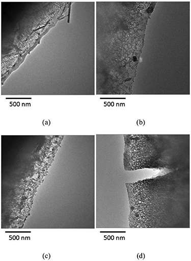
Figure 17. TEM images of (a) fresh aluminium and aluminium stored in an LIB electrolyte (1.2 M LiPF6 in EC, EMC (3:7)) at (b) 4.3 V, (c) 4.9 V, and (d) 5.3 V. Significant cracking of the aluminium can be seen in the sample stored at 5.3 V for one week. Reproduced from [23]. © IOP Publishing Ltd. All rights reserved.
Download figure:
Standard image High-resolution image5.2. Effect of electrolyte
As mentioned previously, a protective layer is formed on aluminium current collectors in LiPF6 based LIB electrolytes. This layer is made up of an inner layer or air formed Al2O3 and an outer passive layer of AlF3. This layer prevents significant aluminium corrosion from taking place during LIB operation.
The composition and presence of impurities in the electrolyte can influence the formation of the passive layer. For example, Al(OH)3 was observed via XPS on the surface of an aluminium current collector, which was suggested to have formed due to the presence of water contamination in the electrolyte [80]. The use of LiPF6 over other electrolyte salts (such as amide salts) has been observed to improve aluminium corrosion resistance during LIB operation [76, 80]. LiPF6 based electrolytes form fluoride-rich passivating films on the aluminium that increases the long term resistance. Despite this positive effect on aluminium, fluorinated electrolyte salts (especially LiPF6) decompose to form HF which can contribute significantly to overall LIB degradation (as discussed in section 5). Whilst there is therefore some interest in using electrolytes that do not contain fluorinated salts, it will be important to consider the decreased corrosion resistance of aluminium when optimising such systems [13, 84 – 88].
Electrolyte salt concentration has also been observed to influence the corrosion resistance of the aluminium current collector. Zhang et al performed anodic polarisation tests in solutions of LiPF6 in EC/DMC, varying the salt concentration from 0.001 to 1 M [75]. It was found that the salt concentration must exceed 0.05 M in order to form a sufficiently protective film on the aluminium.
The presence of HF impurities was found to actually suppress the dissolution of aluminium in some cases [1]. When HF was added to an electrolyte containing LiN(CF3SO2)2, the formation of pits was suppressed on an aluminium electrode. It is thought that the addition of HF facilitates the formation of a more protective AlF3 passive film. In LiPF6 based electrolytes, the successful passivation (AlF3 on the Al2O3 surface of the aluminium metal) is found to provide sufficient protection to corrosion attack. Again, the implications of this suppressed corrosion due to the AlF3 film have not been sufficiently studied, however it would be valuable to understand its contribution to long term LIB electrochemical performance.
5.3. Effect of aluminium microstructure and surface conditions
The microstructure and surface conditions, including defects, of aluminium influence the corrosion behaviour in LIB systems as has been demonstrated experimentally. For example, it was found by examining aluminium polarisation curves that pre-treating aluminium by heating to 480 °C delayed the onset of corrosion in LiClO4 in EC/DME [27]. Different aluminium alloys may also corrode differently. Alloy 1145 (99.45% minimum aluminium) behaved similarly to alloy 1100 (99.0% minimum aluminium and 0.12% copper) when cycled 100 times in LiPF6 in PC/DEC. However, electrochemical impedance spectroscopy indicated that alloy 1145 may have better corrosion resistance upon extended cycling [26]. Iwakura et al performed potentiostatic tests that concluded that the electrochemical stability of aluminium in LiClO4 in EC/DEC increased with aluminium purity; however, this difference was negligible in LiPF6 in EC/DEC as the protective effect of the fluorinated passive film dominates [13].
Defects such as mechanical holes and native grooves may form during the aluminium foil manufacturing process. Similar defects may also form during cell assembly. Such defects can act as initiation sites for the pitting corrosion process [89, 90]. Zhang et al used SEM and EDX to propose that pitting on aluminium is also initiated by mechanical damage to the aluminium current collector that may occur during the process of casting the cathode slurry onto the current collector [91]. Yang et al used tweezers to purposely scratch the surface of an aluminium foil [76]. Obvious corrosion was observed with SEM at the scratch site after cyclic voltammetry experiments.
Crevice corrosion has also been observed on aluminium foil when it is coated with a porous cathode [27, 89, 92, 93]. The porosity of the cathode coating enables electrolyte infiltration, ensuring good contact with the electrode's active material. This porosity however, also enables the development of localised occluded sites, and potentially therefore crevice corrosion. Such corrosion can be seen—figure 18 shows an SEM image of an aluminium current collector, coated with an LiFePO4 cathode and anodically polarised at 100 μA cm−2 for 36 h in an LiPF6-based battery electrolyte [92]. Part of the porous cathode has been removed, revealing the corroded surface of the current collector. In this paper, the authors investigated the corresponding degradation of overall battery performance observed upon corrosion of the aluminium foil (as can be seen in figure 19). Power fade and capacity fade have been measured to increase significantly with increasing crevice corrosion for LiNi0.8Co0.15Al0.5O2 vs. graphite cells cycled at 25 °C [89]. It can be seen that aluminium corrosion correlates directly to the overall degradation in LIBs. Unfortunately such studies that directly investigate the implications of current collector corrosion on LIB performance are limited however it is clear that this understanding will be vital for enabling the development of better batteries.

Figure 18. SEM image of the surface of an aluminium foil coated with an LiFePO4 cathode and anodically polarised at 100 μA cm−2 for 36 h in 1 M LiPF6 in a mixture of EC and DMC (1:1) electrolyte. Most of the cathode has been removed to expose the corroded surface of the aluminium current collector. Reproduced from [92]. © IOP Publishing Ltd. All rights reserved.
Download figure:
Standard image High-resolution image
Figure 19. Graph of percentage power fade and capacity fade versus the percentage of corroded area of an aluminium current collector from aged commercial LiNi0.8Co0.15Al0.5O2 vs. graphite cells with an LiPF6 based electrolyte (1.2 M LiPF6 in EC, EMC (3:7)). Adapted from [89]. © IOP Publishing Ltd. All rights reserved.
Download figure:
Standard image High-resolution image
6. Conclusions
This review summarised the key findings of lithium ion battery current collector degradation and highlighted areas for further study. Although it is evident that significant current collector corrosion is present under both normal and extreme operating conditions, their degradation is generally not considered widely in the context of overall LIB degradation mechanisms. The implications of current collector degradation are also not fully understood, however it is clear that their corrosion can have significant impact on cell performance. The chemistry of LIBs is complex and interlinking, and further work needs to be carried out to deconvolute all the degradation effects that contribute to cell fading, allowing for their mitigation. For example, understanding how dissolved current collector metal ions that are redeposited on electrode SEIs influence the SEI properties will be of importance. An understanding of how current collector degradation contributes to overall cell degradation will enable us to better understand the contribution of other degradation mechanisms too. Due to the complicated nature of LIBs, in situ and in operando techniques will play an important role in developing our understanding of their degradation mechanisms and how they contribute to overall cell performance. Thus far, studies that correlate current collector degradation to overall LIB degradation are limited in number; this topic should be the focus of future studies. Understanding from both the fields of corrosion science and LIB science is required to fully understand the behaviour and degradation of LIB current collectors, forming new perspectives that can enable significant improvement in future battery performance.
Data availability statement
No new data were created or analysed in this study.