Flow Level Pressure
Level Sensing in Harsh Environments with Guided Wave Radar
Jun 23 2014
Author: Trevor Dunger on behalf of ABB Ltd
When you need to take a level reading in a tank full of molten sulphur or some other low dielectric material, a non-contact sensor may not be the way to go. Trevor Dunger, ABB’s Level and Pressure specialist, explains why.
Guided wave radar has established itself as a leading technology for measuring the level of bulk solids, liquids and everything in between. With no moving parts, it works well in harsh chemical environments, under widely varying operating temperatures and on low dielectric materials. Process engineers who work with molten sulphur, liquid ammonia, petrochemicals and other hard to measure media have welcomed the simplicity of integrating guided wave radar devise with most digital communication protocols to obtain data on the contents of tanks, silos, hoppers, bins, mixing basins and vessels. Let’s take a look at the way guided sensors stack up against other time-of-flight technologies such as through-the-air radar –radar and ultrasonic sans then at some application guidelines.
Guided wave technology theory
Radar works by measuring the time of a transmitted signal. Known more accurately as time domain reflectometry, the process entails sending microwave s pulses down through the material of interest and all the way to the bottom of the vessel. When a pulse reaches the product, the beam undergoes a change in impedance caused by the product’s dielectric. Part of the pulse is reflected back to the receiver, which measures the exact duration of time between the departing and the retuning signal, analyses it and displays the product levels as distance in feet, meters or other units.
Through air radar technology was among the pioneers in noncontact level measurement, but false echoes were and remain a significant t problem. Simply pointing a radar transmitter toward the bottom of a silo allows unguided waves to bounce off the sides of the vessel, creating spurious retuning signals that must be cancelled out at the receiving end. Moreover, there are often internal obstructions, such as piping, nozzles and ladders, that can produce unwanted signals. The underlying cause is that the radar beams radiate from the transmitters in an ever widening cone. A similar problem presents itself in ultrasonic measurements, where divergent angles of up to 20 degrees are common.
In guided wave technology, the radar beam is focused by a probe or “waveguide” in the form of a specially designed metal rod or cable that is inserted into the product to be measured. This guide serves to concentrate the radar signal into a smaller-diameter (often < 12 in) cylindrical pattern along the probe length and so prevent dispersion in the vessel. The results are better performance and reliability. Furthermore, it is not necessary to program a unit to ignore spurious readings from the sides of the vessel.
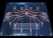
Guided Wave vs Through-air Radar Signal Strength
In addition to problems with pulses returned from the vessel walls and objects inside the tank, noncontact radar units are very sensitive to changes in process conditions such as product build up, foam, turbulence and condensation. Similarly, ultrasound can be adversely affected by tank conditions and vapour phases that affect the speed of sound. While it might seem that the SNR could be improved by increasing the strength of the transmitted radar signal, it isn’t that simple. Loop powered devices by their very nature operate on a tight energy budget. Through-air level sensors use more energy because of the wide-beam spread of the microwaves. Guide-wave radar uses energy much more efficiently by focusing it along a probe and can therefore achieve an optimum SNR even with the limited energy available.
Response time
To weed out spurious signals, through-air radar and ultrasonic technologies use fuzzy logic to assign each target a probability level. The requisite signal processing slows both the response time and the update rate. Guided-wave radar can take up to 10 readings/s; with no additional filtering necessary, the update rate can be similarly fast.
Dielectrics
Through-air radar level sensors don’t work well on low-dielectric media because the pulses pass partially through, rather than reflect off them. In both guided wave and through-air radar, the coax cable carrying the signal from the transmitter to the product typically has an impedance of 50 Q Ideally, if that impedance could be maintained along the radar beam’s entire length of travel, all of the transmitted signal would reflect off the product. In actuality, though a large change in impedance occurs when going from coax to air and causes a substantial signal loss.
In guided-wave radar, the probe is housed in a stainless steel tube that acts as a ground plane to help channel the microwave energy and give the entire assembly a coaxial structure. ,It thus maintains constant impedance along the entire waveguide, allowing the sensor to detect more subtle dielectric changes and correctly indicate product level. Through-air radar can also use a similar pipe arrangement to measure lower dielectrics, but this mode of operation is both more susceptible to build-up and dependent on pipe configuration and construction.
Guided-wave radar transmitters also allow special probe configurations to perform indirect measurements by taking into account the velocity change of the pulse as it travels through the medium. In this manner, very low dielectric products, typically down to 1.3, can be measured in applications where other methods have failed in the past.
Measuring Long Spans
Modern radar transmitters can measure levels in silos and tanks more than 200 ft. tall. In general, it is extremely difficult to obtain high-resolution readings over such distances, given that radar waves travel at a speed of ~ I ft/ns. A 100 ft. silo might contain only 4 ft. of product, meaning that the return time for a reflected wave is only 8 ns less than it would be for an empty tank. To obtain quarter-inch accuracy for such levels, the sensor must measure in increments of picoseconds.
Some guided-wave radar and through-air transmitters use specialized electronic circuitry that includes stable ramp generators. These produce a signal waveform that duplicates the reflected waveform, albeit in a slower time frame. With sophisticated electronics, such devices can achieve resolutions of tens of thousands of an inch over a whole span-accurate enough to satisfy most applications.
Application Guidelines: Product Caking and Build-up
For industries dealing with products that cling to everything they touch, such as molten sulphur as it dries and the paraffin wax common in petrochemical processes, obtaining accurate levels has long presented difficulties. Guided-wave radar level transmitters that rely on coaxial, as well as dual-rod or dual cable waveguides, are at a particular disadvantage here. Problems arise when product build-up bridges the gap between the two rods, rendering the unit inoperable because of the modified impedance between the two wires. The preferred solution calls for the use of a single cable or rod hung in the tank; build-up on a single guide will have minimal effect on transmitter operation. This configuration is limited to higher dielectrics unless the single probe/cable assembly is inserted into an outer stilling well, making it suitable for measuring lower dielectric media.
High-Turbulence Vessels
Both guided wave and through-air radar can be configured to operate in highly turbulent environments, while the former, with its narrower beam, provides better performance under these conditions, there are special requirements.
Installing a stilling well around the probe or the through-air signal can help maintain a more constant level reading. The stilling well, often <=4 in. in dia., should have holes drilled along its length to allow the product to remain in full contact with the radar signal. (The same technique is used for through-air radar, but requires precise stilling well construction with tight tolerances and special welding. Installation and alignment are also critical, and improper setup can sometimes cause erroneous readings.)
The restrictions are not so severe for guided-wave radar. The waveguide causes the signals confined within it to glide past any cut-outs and head straight down to the product, so turbulence has little effect.
Ensuring Optimal Configuration
Easily configured systems surely head the wish list of process engineers- nothing is more frustrating than attempting to shoehorn a universal-purpose transmitter into a particular application that comes with built-in headaches.
Manufacturers of guided-wave radar level sensors offer a full range of transmitters, mountings, couplers, and probes to satisfy nearly any special requirements. For example, the variety of rigid and flexible probes that house either a single or a coaxial cable, some of which can be bent to accommodate unusual tanks, bins, or silos, means the radar units can arrive from the factory already configured. Some probes can even be cut to length in the field. In Secunda, South Africa, the ability to send a radar beam around a 90° corner by using a guided-wave cable allowed accurate measurement of levels in a cooling tower.
Mounting a guided-wave radar transmitter is less critical than mounting a through-air device, which relies on precise configuration of the antenna. Guided-wave can work with apertures as small as a 3/4 in NPT opening. In many cases, radar units must be installed in external chambers as, for example, when they are replacing mechanical units. Special instrument enclosures are sometimes required. Stainless steel is particularly suited to offshore uses, where saltwater will corrode even powder-coated aluminium. Some transmitters are housed in explosion proof enclosures. Some manufacturers will even create custom, one-off designs.
Monitoring bromine levels nearly always requires a special mounting and probe with hermetic seals, and tanks of hydronuoric acid demand probes made of Monel rather than stainless steel. Configuration concerns should also include the transmitter’s communication capability. Many radar units display results locally with a built-in scrolling LCD that offers measurements in a field -selected choice of inches, feet, millimetres, centimetres,
meters, or even percentages. Finally, a device’s ability to seamlessly communicate the data throughout a processing plan t’s business system is equally important.
Guided-wave units offer not only 4-20 mA output but also a variety of digital communications capabilities such as Hart.
Summary
Guided-wave radar level sensors can accurately measure a broad range of challenging products under adverse conditions such as low-dielectric materials, caustic chemical environments, and high operating temperatures and pressures. The technology is becoming the preferred method for use on harsh media, including crude oil, butane, propane, molten sulfur, liquid ammonia, plastic pellets, powders, fly ash, slurries, sludges, acids, and chlorine. The sensors are easily configured to both new and existing applications, and a wide choice of communication protocols is available. Due to their straightforward design and operating frequency of < I GHz, the sensors are often less expensive than comparable through-air devices.
Digital Edition
PIN 25.1 Feb/March
March 2024
In This Edition Safety - The technology behind the ION Science Tiger XT - Safety with ammonia and LOHCs as hydrogen carriers Analytical Instrumentation - Discussion on new tribology te...
View all digital editions


Events
Apr 28 2024 Montreal, Quebec, Canada
Apr 30 2024 Birmingham, UK
May 03 2024 Seoul, South Korea
May 05 2024 Seville, Spain
May 06 2024 Riyadh, Saudi Arabia