Safety
Hazardous Environment – Focus on the Area of Use for Device Selection
Aug 18 2014
Author: CorDEX Instruments Ltd. on behalf of COEX Ltd
The phrase “intrinsically safe” is often used generically to describe products destined for hazardous (explosive) areas, when, in fact, the term is actually one of a number of methods for enabling a product to be used within a hazardous (explosive) environment. This kind of term is referred to as a protection concept.
Further examples of protection concepts are:
• Explosion-proof,
• Purge and Pressurised,
• Encapsulated.
Unfortunately, the use of the term intrinsically safe as a catch-all term is used frequently, if incorrectly. For example, when searching for a camera designed for hazardous areas, the norm would be to search for “intrinsically safe camera,” where in fact there are cameras that use intrinsically safe, explosion-proof and purge and pressurised protection concepts.
This generalization causes problems at some levels. Users can be fixated on obtaining an “intrinsically safe” device, when in fact the means or protection may actually be irrelevant; it is the environment in which the device is required to safely operate within that is important.
For example, the explosion-proof protection concept enables a device to be safely used within a Class I, Division 1 environment. However, intrinsically safe devices have a number of safety levels, meaning a device that is certified as intrinsically safe may not be acceptable in the same areas as one certified as explosion proof.
Basically, the area determines the device selection, not the protection concept. More on this later.
Protection Concepts
If we address a few of the more common protection concepts, we can see they differ in the method used to create a device that is deemed safe for use within a potentially hazardous (explosive) area.
Explosion-proof
This was the first method of creating a “safe” device. Explosion-proof, referred to in Europe as flameproof, is a means by which a device with higher power ratings is encased within an enclosure. The enclosure itself does not prevent explosive gas from entering, nor does it prevent a spark from occurring within.
The enclosure is designed to:
(a) contain the initial overpressure caused by an internal ignition, and
(b) allow the expanding gas to escape in a controlled manner by means of carefully designed and calculated gaps known as flame paths.
Flame paths are not proprietary information. They are defined in the explosion-proof standards and have been calculated over the years as the minimum safe gap allowed for a specified volume and intended target location.
The purpose of flame paths is to allow the expanding hot gas to exit the enclosure via a series of gaps. As the gas expands into the outside world via these gaps, it cools to the extent where it no longer has sufficient energy to cause an explosion outside of the enclosure, hence rendering the facility safe. The downside is the equipment itself is generally heavy due to the strength required to contain any explosion. As such, the creation of portable explosion-proof equipment is generally not undertaken.
Typical examples of flameproof devices are motors and switchgear, whose energy is far above that required to ignite the area into which they must operate.
Purge and Pressurised
Purge and pressurised is a protection concept intended to effectively create a safe area within an enclosure into which uncertified equipment is installed within “safe-area” equipment. In this method, an inert gas, such as nitrogen or argon, is flooded into an enclosure creating a non-incendiary environment.
Purge and pressurised specifics change from location to location, however, in some instances, a control system is required to monitor the gas pressure. If a leak in the inert gas is detected by way of a pressure drop, the control system automatically shuts down power to the enclosure, de-energising internal components rendering them safe until gas is refilled.
The use of the term “purge” in this protection concept is of particular interest here. Once gas pressure is lost and the enclosure is ready to be refilled, it must be purged with inert gas for a predetermined period in order to reduce the residual oxygen to safe levels. In many purge and pressurised systems, there are pockets that cannot be adequately purged by a single tapping, therefore a gallery made from a tube or series of tubes may be used to “chase” out oxygen collecting in hard to reach areas.
While purge and pressurised may seem like an obvious route for lighter product design (no need to contain an explosion), the sealing requirements and the need for some local codes for purging make it more prevalent in fixed equipment.
Typical examples of the purge and pressurised protection concept would be control panels, although some cameras have been manufactured and certified using this method.
The upside of purge and pressurised is a much lighter enclosure design. The downside is the inert gas is a consumable, so portable equipment using this concept requires recharging and rep urging.
Encapsulation
Encapsulation effectively attempts to perform a similar function to purge and pressurised in that the explosive atmosphere is prevented from reaching critical components or equipment by means of hard setting encapsulant.
However, this encapsulant must be of a particular type, which itself must be tested to withstand significant environmental stresses intended to simulate a lifetime of field use. These tests are by no means simple and an entire design can be failed based solely on the material used to encapsulate it.
Additionally, accessibility to the circuit (in the context of an electronic product) is sacrificed as the protection concept is based totally on coverage by the encapsulant. On the positive side, there are minimal circuit restrictions once the encapsulant has been tested.
Encapsulation is not accepted in North America as a protection concept.
Intrinsically Safe
Intrinsically safe as a protection concept is defined as limiting the electrical energy available for ignition. It is sometimes assumed, albeit incorrectly, that this refers only to voltage and current limitations.
In reality, electronic circuits are not only severely limited on voltage and current, but also on inductance and capacitance coupled with strict physical requirements to prevent short circuiting of safety components and/or individual components exceeding the intended auto-ignition temperature of the target environment under a fault condition.
With an intrinsically safe circuit, the battery itself must be tested separately. The use of higher voltage Lithium Ion batteries is rare since they can explode under a fault condition. More commonly implemented secondary (rechargeable) cells use NiMH chemistry which is less volatile.
Many intrinsically safe devices use primary (non-rechargeable) cells. This is more of an advantage as in recent years the chargers themselves must be deemed “associated” devices and be certified
as part of the entire product. There is a certain logic here; if a standard battery charger is used on a certified battery and causes damage, how can we be sure the battery remains safe? The answer is we can’t be sure, therefore, the charger itself must now be tested and certified.
More restrictions!
Over the years, I have heard many highly intelligent, educated people refer to intrinsically safe as a “wrapper” for a non-intrinsically safe device.
If only this were true!
To illustrate, let’s just say we have jumped through the hoops and now have an electronics design that complies with the standards and is intrinsically safe. It would be simple to assume that because the electronics are now safe, the packaging is irrelevant.
Unfortunately, that is not enough. Another significant source of energy is static electricity. If a polymer case is used in the design of an intrinsically safe device, then the plastics themselves must be tested to be anti-static. This process involves conditioning - again - and then a surface conductivity test to confirm that a charge cannot be created.
Even if all these challenges are successfully met, the unit must still pass what is called an ingress protection or IP test and a drop test.
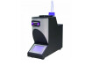
The drop testing requirements for an intrinsically safe device are severe. In the case of the camera shown in Figure 2, the entire device is frozen to -10 degrees C for an extended period. Then the device is dropped multiple times onto concrete.
If the drop test does not result in noticeable damage, the IP testing is subsequently performed ON THE SAME TEST SAMPLE.
Quality Control
Now that we have established the design parameters, created a product and had it certified, we can start selling it, right?
Unfortunately, not!
Quality control is a major challenge with the creation of any explosive area device. As a safety-related device, the control and repeatability of manufacture is paramount. In Europe, ATEX certified equipment requires a separate Quality Assurance Notification (QAN) for the device to be legally sold. This is different from a standard ISO 9001:2000 quality management system and far more stringent with respect to inspection, testing and acceptance. For Nationally Recognised Testing Laboratories (NRTL) certified devices, additional quality control is needed, as are additional audits. This is the case even if the manufacturer already manufactures ATEX equipment and vice versa.
As a manufacturer adds certification marks to the device, the requirement for additional quality control and subsequent third-party audits also increases.
Typically, for devices certified for use in the United States or Canada, these audit frequencies are once per quarter. For European ATEX certified products, the audit is generally on an annual basis.
Conclusion
Whether the device uses intrinsic safe, explosion-proof, purge and pressurised, or any other protection concept, the aim is the same: To create a device or system that is safe to use in the environment for which it is intended.
Typically, hazardous area devices are more expensive than those intended for use in safe areas and it is easy to see why.
The challenges and risks associated with certification mean that design cost and time are dramatically increased. Once a device is certified, the cost to manufacture is also far higher than for a non-certified unit. Special material and processes, increased quality control and multiple audit costs result in a higher cost to the end user.
However, this price is insignificant when compared with the time required to raise permits for non-certified devices, not to mention the potential cost of fines and litigation should a non-certified device cause harm by virtue of its use.
About the Author
Tony Holliday currently serves as Director at a number of design and manufacturing establishments. Holliday began his careers as a Design Engineer creating intrinsically safe and explosionproof metering and control systems primarily for use in the Oil & Gas Industry and progressed into automated switchgear design and commissioning before taking a role as International Sales Manager for Cockburn Thermal Imaging Ltd. Subsequent roles include Sales & Marketing Director at Hawk IR International Ltd. and General Manager for Fluke Electronics IR Window business.
A published technical author and presenter, Tony brings a wealth of experience and knowledge across a broad base of industrial sectors.
Digital Edition
PIN 25.1 Feb/March
March 2024
In This Edition Safety - The technology behind the ION Science Tiger XT - Safety with ammonia and LOHCs as hydrogen carriers Analytical Instrumentation - Discussion on new tribology te...
View all digital editions


Events
Apr 22 2024 Hannover, Germany
Apr 22 2024 Marrakech, Morroco
Apr 22 2024 Muscat, Oman
Apr 22 2024 Rotterdam, Netherlands
Apr 23 2024 Singapore